
Engineering of Water Systems

Standby and Backup Systems: Generator Sizing for Electric Motors
By Ed Butts, PE, CPI
We have reviewed the basic terminology and theory of generators and fundamental sizing techniques in past columns. In this latest look at generators, we will examine the primary use of generators in the water well industry: the application and sizing of generators for electric motors.
Generator Sizing for Motors and Other Loads
Going to a genset dealer and guessing the size or buying the best or cheapest generator available without any other consideration is clearly not the best approach. It is always better to delve into the specific power generation requirements before making a choice, particularly with electric motors.
This involves the considerations listed in the following steps which will result in making the proper decision. Therefore, these steps are recommended when sizing or specifying a generator set.
1. Understanding and Inventorying the Number and Types of Loads
Loads on a generator will vary according to the type of load. There are two primary types of loads a generator will experience: resistive and reactive.
A resistive load is one in which the circuit is comprised of resistance only, such as incandescent lights, toaster, oven, or water heater elements, televisions, or unit or room electric heaters.
A reactive load, on the other hand, includes air conditioners, motors (inductance) and fluorescent light fixtures (capacitance). It is a load which is carried by an alternating current generating system in which the current and voltage are 90° out of phase (for a purely reactive load) which is measured in volt-amperes
or kilovolt-amperes (kVA).
Generators are typically rated and sized according to their kilowatt or kW rating with one kW equal to 1000 watts for continuous amps and skVA for motor starting power. All loads should be inventoried and listed as required for operating amperage, voltage, phase, and wattage.
In addition, motor nameplates are consulted to obtain HP, code letter, efficiency, and power factor. A careful and complete inventory of the intended loads can save a great deal of grief from under- or over-sizing a generator. Many AC devices and machines are rated in either amperes and voltage or wattage with this relationship for each type:
- For an AC 1Φ Resistive Load: Wattage = Amperes ×
Voltage - For an AC Single-Phase Reactive Load: Wattage =
Amperes × Voltage × Power Factor - For an AC Three-Phase Reactive Load: Wattage =
Amperes × Voltage × Power Factor × 1.732 (√3)
Induction machines are some of the most common types of loads in the electric power system today. These machines use inductors or large coils of wire to store energy in the form of a magnetic field.
When a voltage is initially placed across the coil, the inductor strongly resists this change in current and magnetic field, which causes a time delay for the current to reach its maximum value. This causes the current to lag behind the voltage in phase.
Inductors are said to sink reactive power, and to cause a lagging power factor. Induction generators can source or sink reactive power and provide a measure of control to system operators over reactive power flow and, thus, voltage.
Because these devices have opposite effects on the phase angle between voltage and current, they can be used to cancel out each other’s effects. This usually takes the form of capacitor banks (power factor correction or PFC) being used to counteract the lagging power factor caused by induction motors.
2. Calculating Motor Loads and Determining Motor Starting Method
Depending upon the type and number of devices and the way the generator is scheduled to be used, there are a few different ways of calculating power requirements for motors:
- Single motor and starting method: Intermittently starting and running (cycling)
- Single motor and starting method: Continuously running once started
- Multiple motors: Intermittently starting and running simultaneously (cycling)
- Multiple motors: Continuously running once started.
All data related to use of an electric motor on a generator, including motor full load and starting (locked rotor current or skVA power), can and should be obtained from the manufacturer for the specific motor contemplated for use.
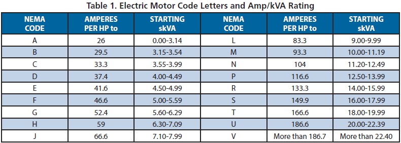
When this information is unavailable, the data contained in Table 1 can be used to determine the full voltage starting locked rotor kVA based on the NEMA Code Letter for all motors while Table 2 estimates the motor efficiency and starting and running power factors for various HP sizes.
This information is basic when sizing a generator for motor loads, but starting of the motors is a task that the designer cannot afford to underestimate or ignore as the method of motor starting has a profound impact on the genset size. The following provides guidance on this critical element of generator selection.

Full Voltage Motor Starting
Motor starting, particularly full voltage (FV)—also known as direct-on-line (DOL) or across-the-line (AOL) starting—is probably the most complex interaction that occurs between a generator set and its applied loads. This is because the results are a function of alternator capability (including both the stator and exciter), voltage regulator capability, engine capability, and governing functions as well as the motor itself and the diverse characteristics of the loads that are actually driven by the motor.
The load demand on the generator set package when a motor is starting at full voltage can best be understood by a review of a typical motor starting curve. The peak kVA demand on the generator set during across-the-line starting occurs at the instant that the motor connects to the generator set and continuously decays as the motor accelerates.
The available motor torque begins at a level slightly higher than at rated speed and continuously increases to a peak between 85% to 90% of rated speed. On reaching about 90% of the rated speed, torque quickly drops to the rated torque.
Whenever the available motor torque exceeds the torque demand, the motor will accelerate. The greater the difference between the two, the faster the motor will accelerate to rated speed. Conversely, if available torque is less than the torque demand, the motor will stall.
These characteristics are common in all motors, but actual values vary considerably in magnitude depending on the characteristics of the specific motor selected. In particular, it’s important to note that high efficiency motors typically have significantly higher peak kVA demands, so it’s important to consider that when doing generator sizing calculations.
Starting a motor, especially at full voltage, demands varying levels of both kW and kVAR components as a motor is starting and accelerating its load to rated speed. Consequently, a critical evaluation of a genset’s ability when starting one or more motor loads demands an evaluation of the entire system to serve all these times and magnitude-varying needs.

While most motor-to-pump loads can be considered easy to start, it’s risky to simply assume they won’t push a generator set to or beyond its limits and potentially leave a part of the other loads effectively underserved or cause an overload or shutdown of the genset.

Figure 1. Typical full voltage motor starting curve.
Complicating the problem is the fact that there is no single standard that can be used to provide a basis for the necessary validation and design work. The industry currently depends on a critical evaluation of hardware primarily based on the requirements specified in NEMA MG1-Part 32, and NFPA 110 for fire protection systems.
All electric motors are designed for a Locked Rotor Code (LRC) or Locked Rotor Amps (LRA) condition, often referred to simply as the Code or Code Letter. This is the amount of kVA or amperes at a specific voltage the motor requires to overcome the starting drag and inertial forces needed to accelerate the motor and its load.
When starting motors, large voltage and frequency dips may occur if the generator set isn’t sized properly. Other loads, particularly electronic loads such as uninterruptible power supplies (UPS) or computers connected to the genset, may be more sensitive to voltage and frequency dips than the motor or motor starter and may also cause problems. For example, a rate of change greater than 1 Hz/sec in generator frequency may cause some static UPS units to malfunction.
If the load on the generator set is a single large motor, particularly one requiring a high degree of starting torque, a vast number of problems can occur. They include sustained low-voltage operation that can cause overheating, extended load acceleration times, opening of motor protection devices, activation of engine-generator protection devices, unit shutdowns, and more.

Motor loads cause difficulty because a motor draws higher current when started at full voltage. As shown in Figure 1, starting current is typically six times (600%) the motor’s rated full-load current (FLC). This inrush current stays above 400% of FLC until the motor reaches approximately 80% of its rated speed when it begins to fall rapidly and stabilizes at 100% FLC.
When a motor is started on normal utility power, the high inrush current will cause only a small voltage dip because the utility power source has a higher available primary voltage level. However, when a motor is started on genset power, the high inrush currents can result in a large voltage dip that can inhibit the motor from reaching its operating speed.
Motors have typical starting characteristics with a high inrush current that causes a momentary dip in the generator voltage. The motor must develop greater torque than required by the load. The torque demand for most submersible and deep-well vertical turbine pumps lies below the available torque. The difference between the torque developed by the motor and the torque required by the load determines the rate of acceleration. Since torque is proportional to voltage, any reduction in voltage means a proportional reduction in torque.
The data contained in Table 3a for various types of 120- and 240-volt, single-phase motor loads and Table 3b for other 240V loads provide estimated amperage and kW values for typical electrical devices and appliances used in residential and light commercial settings. Table 4 provides a convenient way to convert kW and kVA to amperage.

Reduced Voltage Motor Starting
Although a voltage dip often causes various problems, a controlled and momentary reduction in voltage at the motor terminals can be useful and beneficial to generator sizing, but only when an associated reduction in motor torque is acceptable.
Since the available motor torque from a reduced voltage starter generally exceeds the torque required to start and accelerate a centrifugal or well pump at rest, this is often an acceptable method of motor starting when a generator is used.
Reducing the motor starting kVA can also reduce the required size of the genset, reduce the voltage dip, and provide a softer and steadier start for both the motor and its load, an important consideration on a deep-well vertical turbine (lineshaft) pump.
When sizing gensets, the designer must first determine the acceptable level of motor torque required during starting or the pump may accelerate slowly or even fail to reach full speed (stall), ultimately causing motor or pump damage.
Many types of reduced voltage starters are available for use with generators, but not all will necessarily work with every application. For reference, the information in Table 5 summarizes the various types of motor starting methods.

Notes for Table 5
(1) Values are typical but not guaranteed. Various values of skVA, starting current, and torque are highly dependent on the motor and starter design. Consult motor or starter manufacturer for specific data.
(2) Percentage of full voltage means the percentage of the respective parameter at full voltage conditions. FLA values reflect the percentage of inrush (full voltage starting = 600% to 700%) amperages based on the motor’s full load amps.
(3) Though a voltage dip often causes various problems, a controlled reduction in voltage at the motor terminals can be beneficial but only when a reduction in motor torque is acceptable. Reducing motor starting kVA can reduce the required size of the genset, reduce the voltage dip, and provide a softer start for the motor loads. When sizing gensets, the acceptable level of motor torque required during starting must be ascertained or the loads will accelerate slowly or even fail to reach full speed (stall), ultimately causing motor damage.
(4) Solid-state soft starters can be adjusted to vary starting torque, acceleration ramp time, and current limit for controlled acceleration of a motor during starting. For the purposes of sizing a genset, the current limit adjustment reduces the inrush current and may be used to reduce the starting kW and kVA requirement on the generator.
The range of available current limit settings is typically between 150% to 600% of full-load current. A 600% current limit setting on a solid-state starter results in a genset sizing that’s about the same as an across-the-line starting method while a 300% current limit setting reduces starting kVA by 54%. Use of a current limit setting will also reduce the torque available to the motor.
Typically, for most well pumps, an extended acceleration ramp time and lower current limit will lessen voltage and frequency distortions and water hammer potential, thus providing smoother flow transitions. A downside to the use of solid-state motor starters during operation is their use of silicon-controlled rectifiers (SCRs) that can distort voltage waveforms.
To compensate for these components, the genset will need to be oversized when kept online after startup. The basic recommendation is to use twice the running kW load, except when an automatic bypass is used. If the starter is equipped with an automatic bypass, the SCRs are in the motor circuit only during starting. Therefore, once the motor has started and is running, the bypass contactor closes and shunts out the SCRs. In this case, the voltage distortion during starting can be ignored and additional generator capacity is unnecessary.
(5) All versions of variable frequency drives (VFDs) are inherently current-limiting and reduce starting kW and kVA. The current drawn by these drives is nonlinear (produces harmonics), which causes a distorted voltage dip across the reactance of the generator. Since VFDs are nonlinear, additional generator capacity sizing, as with a solid-state starter, must be added to keep voltage distortion to a reasonable level of about
15% total harmonic distortion (THD) or less.
The larger the generator, the greater the reduction in impedance of the generator. This reduces the effects caused by harmonic current distortion. For six-pulse VFDs, a typical generator sizing factor would be to use twice the running kW of the VFD. This will offset any reduction in starting kW and kVA. If it is the pulse width modulated (PWM) type or includes an input filter to limit current distortion to less than 10%, the sizing factor can be reduced to 140% over the running kW of the VFD.
Final Thoughts
Extreme care should be observed when applying reduced voltage starting to generators and electric motors. Submersible pump motors have limited and specific application guidelines for their use on generators and allowed starting methods. In all cases, the manufacturer’s datasheets should always be consulted when applying motors to generators and reduced voltage starters.
One item often overlooked with reduced voltage starters is the amount of starting torque that is reduced due to any additional voltage drop from the generator to the motor controller. This is a critical design factor since any transient voltage dip during startup will further reduce the starting torque.
For example, if a motor is being started with an autotransformer starter set on the 65% voltage tap, the motor will experience only 42.25% of its full voltage equivalent starting torque available to it upon startup.
If the supply voltage happens to momentarily dip 20% during the transient phase, the resulting voltage at the motor terminals will amount to only 80% of 65% of the rated voltage, 0.80 × 0.65 = 0.52, or 52% of full voltage. Squaring 52% to determine torque (0.52 × 0.52) results in a net value of 27% (0.27) of the full voltage starting torque, not the originally anticipated 42.25%.
This severe loss of motor starting torque can potentially result in stalling of the unit during start or acceleration. This is far more likely to occur with a deep-well vertical turbine or submersible pump.
______________________________________________
This concludes the third part of a four-part series on generators. We will wrap things up in the October issue.
Until then, keep them pumping!
 Ed Butts, PE, CPI, is the chief engineer at 4B Engineering & Consulting, Salem, Oregon. He has more than 40 years of experience in the water well business, specializing in engineering and business management. He can be reached at epbpe@juno.com.
Read the Current Issue

you might also like

The company looks forward to seeing attendees in Las Vegas for Groundwater Week 2026.


The promotion is part of CPF’s ongoing succession planning and organizational alignment efforts.


